Effective Control of the Optical Bistability of a Three-Level Quantum Emitter near a Nanostructured Plasmonic Metasurface


1
Institute of Theoretical Physics and Astronomy, Vilnius University, Saulėtekio 3, LT-10257 Vilnius, Lithuania
2
Materials Science Department, School of Natural Sciences, University of Patras, 265 04 Patras, Greece
3
Department of Physics, School of Applied Mathematics and Physics, National Technical University of Athens, 157 80 Athens, Greece
*
Author to whom correspondence should be addressed.
Photonics 2021, 8(7), 285; https://doi.org/10.3390/photonics8070285
Submission received: 30 May 2021 / Revised: 14 July 2021 / Accepted: 15 July 2021 / Published: 17 July 2021
(This article belongs to the Special Issue Plasmonic Metasurfaces)
Abstract
:
We study, theoretically, the phenomena optical bistability and multistability of a hybrid quantum-plasmonic system immersed within an optical ring cavity. The hybrid quantum-plasmonic system consists of a three-level V-type quantum emitter and a two-dimensional plasmonic metasurface of gold nanoshells. The quantum emitter and the plasmonic metasurface are placed in close proximity to each other so that a strong quantum interference of spontaneous emission occurs, which enables the strong modification of optical-bistability/ multistability hysteresis curves. Along with this, the strong interaction between the emitter and the plasmonic metasurface allows for active control of the corresponding bistable threshold intensity. Furthermore, we show that by varying the metasurface-emitter separation, a transition from bistability to multistability of the hybrid system is observed. Lastly, by introducing an additional incoherent pumping in the system, we have the emergence of phenomena, such as probe absorption and gain, with or without population inversion. The results may find technological application in on-chip nanoscale photonic devices, optoelectronics and solid-state quantum information science.
1. Introduction
Coherent control of light using light is very important in optical computing and all-optical communication. During recent years, optical transistors, all-optical storage and all-optical switching devices based on optical bistability (OB) in two-level atomic configurations have been extensively investigated [1,2]. The OB features in three and multilevel atom-light coupling schemes by means of optical ring cavities were later investigated, both theoretically and experimentally [3,4,5,6,7,8,9,10,11]. Namely, it was demonstrated that quantum interference effects, such as the electromagnetically induced transparency [12], can be used to significantly decrease the OB threshold.
On the other hand, in recent years, there has been great interest in the nonlinear optical effects of quantum systems in the vicinity of plasmonic nanostructures and metasurfaces. It is known that nonlinear effects in these structures can be significantly modified and even enhanced due to the strong exciton-plasmon coupling for quantum systems near plasmonic nanostructures, the subwavelength concentration of the electric field, as well the significant change of the spontaneous decay rate of the quantum systems due to the plasmonic nanostructures.
Various phenomena have been studied in such media, including the manipulation of spontaneous emission [13,14,15,16], Fano effects in energy absorption [17,18,19,20], slow light and optical transparency [21,22,23], enhancement of the refractive index [24], modification and enhancement of the Kerr nonlinearity [25,26,27,28], four-wave-mixing [29,30], inversionless gain [31,32,33,34,35,36], OB or optical multistability (OM) [37,38,39,40,41,42,43,44,45,46,47,48,49], and many others [50,51,52]. The contemporary fabrication methods [53,54,55,56] for realizing plasmonic nanostructures incorporating quantum emitters [57] enable the experimental verification of the above phenomena.
In this work, we consider a closed V-type quantum emitter that is placed next to a plasmonic nanostructure, which, altogether, constitutes the quantum sample. The quantum sample (emitter+nanostructure) is placed inside a unidirectional optical ring cavity. The focus of the present study is to analyze, theoretically, the phenomenon of OB occurring in the quantum sample placed in this type of cavity.
In particular, we found that the rate of incoherent pumping, the distance of the quantum system from the plasmonic nanostructure, the probe detuning, as well as the doublet splitting dramatically influenced the OB as well as the OM, allowing for a robust manipulation of the corresponding threshold intensity and hysteresis loop. Namely, we demonstrate that by varying the distance of the quantum system from the plasmonic nanostructure, one can achieve a transition from the regime of OB to OM.
2. Model and Equations
2.1. Hamiltonian and Master Equations
Figure 1a shows a three-level quantum V-type emitter with two closely lying upper states
and
, and a lower state
.The quantum emitter is surrounded by a vacuum and is placed at a distance d from the surface of a plasmonic metasurface, as illustrated in Figure 1b. The upper states
and
characterize two Zeeman sublevels (
,
), while the lower state
is a corresponding level with
. The dipole moment operator is, then,
where the right-rotating (
) and left-rotating (
) unit vectors are defined by
, while
is taken to be real.
We assume that the above quantum emitter is illuminated by a linearly polarized electromagnetic plane wave in which case the electric field is
, where E denotes the electric field amplitude and
is the angular frequency. The laser field couples the transition between state
and states
and
. Under the dipole and rotating-wave approximations, the interaction Hamiltonian describing the light-matter coupling reads
where
is the detuning,
and
. Note that,
corresponds to the energy of state
. The Rabi frequency of the laser field is defined as
. The excited states
and
decay spontaneously to state
with rates
and
, respectively. The frequencies of the transitions from
,
to
fall within the band of surface-plasmon excitations of the plasmonic metasurface of nanoshells. Furthermore, two incoherent pump fields
and
(
) are applied as responsible for pumping populations from the lower state
to excited states
and
via a one-way pump process.
denotes the free-space decay rate of states
and
to state
. Finally, we take that
[15].
Based on the Markovian approximation and the Hamiltonian of Equation (2), the density-matrix equations of the quantum sample read as
The above equations are consistent with the conservation law
with
.
In the above equations,
corresponds to the coupling coefficient between upper states
and
resulting from the occurrence of quantum interference of spontaneous emission in an electromagnetically anisotropic environment [58,59].
Here,
and
are provided by [13,14,60,61,62,63,64]
where
(
) corresponds to the electromagnetic Green’s tensor,
is the position of the quantum emitter and
stands for the free-space electric permittivity. Equations (8) and (9) provide the values of
and
[13,14,60,61,62,63,64]
and
denote the components of the Green’s tensor, where ⊥(‖) corresponds to a dipole oriented normal, along the z axis (parallel, along the x axis) to the plane of the 2D plasmonic metasurface. The spontaneous-emission rates for a dipole oriented normal and parallel to the metasurface are given by
. The degree of quantum interference is provided by
The peak value of quantum interference in spontaneous emission is
[59]. This is possible if we place the quantum emitter close to a surface that possesses a negligible
. If the quantum emitter lies in free space,
, resulting in
suggesting the complete absence of quantum interference in the emitter.
As a plasmonic metasurface, we take a two-dimensional square lattice of dielectric (silica) spheres coated with gold (plasmonic material) [Figure 1b,c]. Such nanostructures are routinely fabricated by self-assembly [65], nanopatterning and nanolithographic [66,67] techniques. The dielectric function of the shell is described by the free-electron Drude model
is the bulk plasma frequency of the metal, whilst
is the relaxation time of the conduction-band electrons. For gold, the plasma frequency
fixing the corresponding length scale of our calculations as
. The electric permittivity of
is taken to be constant,
. In all the calculations that follow, we assumed
. The square lattice of nanoshells has a period of
, whilst the corresponding radii of the sphere and core are
and
, respectively. Explicit relations that provide the electromagnetic Green’s tensor for a two-dimensional lattice of spheres can be found elsewhere [13,68,69].
In the calculations that follow, we take
. d stands for the distance between the quantum emitter and the surface of the plasmonic metasurface of gold nanoshells. We assumed that the quantum emitter is placed opposite the center of a nanoshell of the metasurface. The spectra of
and
were directly taken from Figure 3 in [21], where it was demonstrated that
is suppressed to such degree that it actually becomes significantly lower than the decay rate of the quantum emitter in a vacuum.
is a decreasing function of the separation between the quantum emitter and the plasmonic metasurface.
Moreover, when the emitter is located very close to the metasurface,
becomes much larger than the decay rate in a vacuum. Namely, for distances up to
,
assumes much higher values than the corresponding vacuum decay rate. On the other hand, for distances between
and
,
becomes smaller than the corresponding free-space decay rate.
2.2. Susceptibility
The electric susceptibility of the quantum system describing the absorption and dispersion properties of the weak probe field is written as
where the steady state of the density matrix Equations (3)–(7) are
and
, while
and N are the vacuum permittivity and numerical density of the quantum emitters, respectively.
Calling on Equations (3)–(7), it is easy to find
where
and
. Here,
(
) shows the steady state population of levels
and
describes the coherence term induced by quantum interference of spontaneous emission.
One can decompose Equation (15) into two parts. The first term (containing two sub-terms) comes from the direct transitions
and
and depends on the population inversions (
) (
), while the second term is due to quantum interference when the quantum system is placed in the vicinity of the plasmonic nanostructure and is proportional to the coherence terms
and
.
2.3. Optical Bistability in a Unidirectional Ring Cavity
To characterize the OB features, we consider a medium of length L described by the permittivity of Equation (14) embedded in a unidirectional ring cavity, as illustrated in Figure 1d. The mirrors 3 and 4 are taken as perfect reflectors. The corresponding reflection and transmission coefficients of mirrors 1 and 2 are given by R and T, respectively, with
. For a perfectly tuned cavity and in the steady-state limit, the boundary conditions between the incident field
and the transmitted field
read as [70]
The second term on the right-hand side of Equation (18) describe the multiple-reflection processes between the mirrors of the cavity, which provides the occurring OB. Clearly, for
in Equation (18), bistability disappears. The boundary conditions and mean-field limit determine the transmitted field in the steady-state,
where
is given by Equation (15).
and
correspond to the normalized input and output fields, respectively. The parameter
is the cooperative parameter for a system in a ring cavity.
3. Results and Discussion
Next, we calculate the input–output curves for the quantum-sample (emitter + metasurface) medium immersed in the optical ring cavity and compare them with the case where a medium of solely quantum emitters is placed in the cavity (absence of the plasmonic metasurface). Namely, in Figure 2, we show the OB in the absence of the incoherent pumping
and for the resonance condition
. We considered the case of a degenerate system, i.e.,
, yielding
.
One can see that the OB is already present even in the absence of a plasmonic metasurface (medium of sole quantum emitters) i.e.,
(solid curve). However, by inserting the quantum-sample medium (emitter + plasmonic nanostructure) inside the ring cavity, and for distances
(dot-dashed curve) and
(dashed curve) of the emitter from the metasurface, we observe a significant modification of the area of the hysteresis cycle due to the reduction of the threshold intensity for both the lower and higher branches (the reduction of the higher branch is more dramatic).
The reason for this behavior can be qualitatively interpreted as follows. In the presence of a plasmonic metasurface, very narrow resonances take place at the zero detuning of probe absorption profile (not shown here). In this case, the whole of the absorption spectra is enhanced as
and
decrease with distance. Moreover, the width of the absorption peaks are also reduced with
, leading to very sharp resonant absorption peaks, which may result in a reduction in the threshold intensities for both the lower and upper branches of the OB profile.
The OB features change drastically when we consider a degenerate system (
). In Figure 3, we show the scaled feedback output field versus the scaled input field for
and
and for different values of probe-field detuning. We have assumed that the the V-type quantum emitter in the quantum sample is located at distance
from the plasmonic metasurface. It is clear that no OB can be realized on resonance (
) with the probe field (solid curve).
By slightly increasing the probe-field detuning to
(see the dotted curve), the hysteresis cycle appears, giving rise to the optical bistability. A further increase of
leads the hysteresis cycle to become larger continually with a subsequent increase in the threshold intensity of OB in both the lower and higher branches. Physically, an induced transparency (zero absorption) will occur on resonance (
) with the energy absorption spectra of the quantum V-system, leading to a perfect transmission of the probe laser field.
The slope of dispersion will be positive around the zero detuning, with an exact zero value for the dispersion and optical Kerr nonlinearity at
, leading to no OB features. However, away from zero detuning, absorption, dispersion and Kerr nonlinear effects emerge—namely, there is a significant increase in the probe absorption for larger detunings (not shown here) for which the cavity field can hardly achieve saturation, leading to a subsequent enhancement in the OB threshold intensity.
In Figure 4, we show the effect of distance d from the plasmonic metasurface on the behavior of OB for
,
, and
. We observe that, by varying the distance from
(dot-dashed curve) to
(solid curve), we have a transition from OB to OM with a significant reduction in the OM threshold intensity. Realization of OM in quantum systems near plasmonic nanostructures might find application in all-optical switching or coding elements.
One can see that in this case, there are two S-shaped curves for a certain input intensity domain in the input–output solution. When the input field power is increased from zero, the output intensity of the cavity remains on the lower branch. As soon as the output intensity approaches to the threshold of the onset of first S-shaped curve (lower branch), it jumps up to the middle branch, and, from there, again jumps up to a higher branch (tristability). The OB appears again for the larger distance
(dashed curve). The OB threshold increases again and becomes larger than the OM threshold intensity.
The effect of the incoherent pumping rate r on the OB spectra of the quantum sample is shown in Figure 5, for
and for
. Interestingly, the threshold of OB first decreases by increasing the rate of the incoherent pumping field (Figure 5a). For stronger incoherent pumping rates, the threshold of the OB starts to increase by increasing the rate of the incoherent pumping field, as can be seen in Figure 5b,c.
In Figure 6a, we show the population distributions
and
, and (b) and the lasing spectrum [
] of the probe field versus the incoherent pumping. Here, the most interesting result relies on the creation of three different regimes for the incoherent pumping to create OB. The first regime is for the incoherent pumping
where the system is absorptive and no population inversion exists (red zone in Figure 6b).
The observed OB in Figure 5a can be attributed to the presence of absorption in the medium. The second regime is
where gain without population inversion takes place (green zone in Figure 6b). The OB in Figure 5b can be attributed to such a gain without inversion. Lastly, there is a regime with
where the gain is with population inversion (blue zone in Figure 6b), which is responsible for the creation of OB spectra illustrated in Figure 5c.
In the first regime where the incoherent pumping rate is very weak (r from 0 to
), the absorption decreases by increasing the rate of incoherent pumping field. The reduction in the probe absorption may enhance the Kerr nonlinearity of the quantum system, allowing for direct saturation of the cavity field. This yields a reduction of the OB threshold intensity as observed in Figure 5a.
On the other hand, the coherence between upper states will be destroyed by the stronger incoherent pumping from the lower level to the upper levels (
) as the gain starts emerging in the system. The enhancement of the probe gain increases the difficulty of the cavity field to reach saturation, resulting in an increase in the OB threshold intensity (as observed in Figure 5b,c).
We should point out that the presence of a plasmonic metasurface makes it almost impossible to determine analytically a limit for the gain
as, in this case, the analytical solutions are quite long, complicated and non-informative. We, therefore, used the numerical results to identify the limits for the lasing threshold
. However, we present analytically the limit for the incoherent pumping to make population inversion in the system. Calling on Equations (5)–(7), one can obtain expressions for the population inversion as
Equation (20) shows that the population differences
and
depend on the incoherent pumping rate r as well as the quantum interference determined by
, which is varying by the distance from the plasmonic nanostructure. Plugging equations Equations (10) and (11) into Equation (20), the limit for the incoherent pumping to achieve the population inversion can be expressed as
Clearly, the population inversion is dominant if
, otherwise no inversion appears in the population distributions. These effects are illustrated in Figure 6a.
4. Conclusions
In conclusion, we demonstrated, theoretically, that it is possible to achieve a controllable shift of the OB threshold intensity as well as modification of the hysteresis curve of OB for a quantum sample placed within an optical ring cavity where, for a quantum sample, we referred to a V-type quantum emitter coupled with a plasmonic metasurface. These unique features of the OB are a result of the enormous enhancement of the quantum interference in the quantum emitter imparted by the presence of the plasmonic metasurface, which, in our case, was a square lattice of gold-coated silica nanospheres (a lattice of plasmonic nanoshells).
The effect of different system parameters on the OB were also studied. We found, in particular, that the OB could be switched to OM by varying the distance of the quantum emitter from the plasmonic metasurface. When the quantum system was pumped by an one-way incoherent pumping field, the bistability could appear with absorption and gain, with or without population inversion. The results may find technological application in the realization of more efficient all-optical switches and logic-gate devices for optical computing and quantum information processing.
Author Contributions
Writing—original draft, H.R.H.; Writing—review and editing, E.P. and V.Y. All authors have read and agreed to the published version of the manuscript.
Funding
This research received no external funding.
Data Availability Statement
Data are available from the authors on request.
Conflicts of Interest
The authors declare no conflict of interest.
References
- Gibbs, H.M.; McCall, S.L.; Venkatesan, T.N.C. Differential Gain and Bistability Using a Sodium-Filled Fabry-Perot Interferometer. Phys. Rev. Lett. 1976, 36, 1135. [Google Scholar] [CrossRef]
- Rosenberger, A.T.; Orozco, L.A.; Kimble, H.J. Observation of absorptive bistability with two-level atoms in a ring cavity. Phys. Rev. A 1983, 28, 2569. [Google Scholar] [CrossRef] [Green Version]
- Harshawardhan, W.; Agarwal, G.S. Controlling optical bistability using electromagnetic-field-induced transparency and quantum interferences. Phys. Rev. A 1996, 53, 1812. [Google Scholar] [CrossRef] [PubMed]
- Chang, H.; Wu, H.; Xie, C.; Wang, H. Controlled Shift of Optical Bistability Hysteresis Curve and Storage of Optical Signals in a Four-Level Atomic System. Phys. Rev. Lett. 2004, 93, 213901. [Google Scholar] [CrossRef] [Green Version]
- Cheng, D.C.; Liu, C.P.; Gong, S.Q. Optical bistability via amplitude and phase control of a microwave field. Opt. Commun. 2006, 263, 111. [Google Scholar] [CrossRef]
- Cheng, D.C.; Liu, C.P.; Gong, S.Q. Optical bistability and multistability via the effect of spontaneously generated coherence in a three-level ladder-type atomic system. Phys. Lett. A 2004, 332, 244. [Google Scholar] [CrossRef]
- Li, J.-H. Controllable optical bistability in a four-subband semiconductor quantum well system. Phys. Rev. B 2007, 75, 155329. [Google Scholar] [CrossRef]
- Wang, Z.; Xu, M. Control of the switch between optical multistability and bistability in three-level V-type atoms. Opt. Commun. 2009, 282, 1574. [Google Scholar] [CrossRef]
- Sahrai, M.; Asadpour, S.; Sadighi-Bonabi, R. Optical bistability via quantum interference from incoherent pumping and spontaneous emission. J. Lumin. 2011, 131, 2395. [Google Scholar] [CrossRef]
- Hamedi, H.R.; Khaledi-Nasab, A.; Raheli, A.; Sahrai, M. Coherent control of optical bistability and multistability via double dark resonances (DDRs). Opt. Commun. 2014, 312, 117. [Google Scholar] [CrossRef]
- Hamedi, H.R.; Sahrai, M.; Khoshsima, H.; Juzeliunas, G. Optical bistability forming due to a Rydberg state. J. Opt. Soc. Am. B 2017, 34, 1923. [Google Scholar] [CrossRef]
- Fleischhauer, M.; Imamoglu, A.; Marangos, J.P. Electromagnetically induced transparency: Optics in coherent media. Rev. Mod. Phys. 2005, 77, 633. [Google Scholar] [CrossRef] [Green Version]
- Yannopapas, V.; Paspalakis, E.; Vitanov, N.V. Plasmon-Induced Enhancement of Quantum Interference near Metallic Nanostructures. Phys. Rev. Lett. 2009, 103, 063602. [Google Scholar] [CrossRef] [PubMed]
- Evangelou, S.; Yannopapas, V.; Paspalakis, E. Simulating quantum interference in spontaneous decay near plasmonic nanostructures: Population dynamics. Phys. Rev. A 2011, 83, 055805. [Google Scholar] [CrossRef]
- Evangelou, S.; Yannopapas, V.; Paspalakis, E. Modifying free-space spontaneous emission near a plasmonic nanostructure. Phys. Rev. A 2011, 83, 023819. [Google Scholar] [CrossRef]
- Gu, Y.; Wang, L.; Ren, P.; Zhang, J.; Zhang, T.; Martin, O.J.F.; Gong, Q. Polarized linewidth-controllable double-trapping electromagnetically induced transparency spectra in a resonant plasmon nanocavity. Nano Lett. 2012, 12, 2488. [Google Scholar] [CrossRef] [Green Version]
- Artuso, R.D.; Bryant, G.W. Strongly coupled quantum dot-metal nanoparticle systems: Exciton-induced transparency, discontinuous response, and suppression as driven quantum oscillator effects. Phys. Rev. B 2010, 82, 195419. [Google Scholar] [CrossRef]
- Zhang, W.; Govorov, A.O.; Bryant, G.W. Semiconductor-Metal Nanoparticle Molecules: Hybrid Excitons and the Nonlinear Fano Effect. Phys. Rev. Lett. 2006, 97, 146804. [Google Scholar] [CrossRef] [PubMed] [Green Version]
- Singh, M.R.; Schindel, D.G.; Hatef, A. Dipole-dipole interaction in a quantum dot and metallic nanorod hybrid system. Appl. Phys. Lett. 2011, 99, 181106. [Google Scholar] [CrossRef]
- Kosionis, S.G.; Terzis, A.F.; Yannopapas, V.; Paspalakis, E. Nonlocal Effects in Energy Absorption of Coupled Quantum Dot–Metal Nanoparticle Systems. J. Phys. Chem. C 2012, 116, 23663. [Google Scholar] [CrossRef]
- Evangelou, S.; Yannopapas, V.; Paspalakis, E. Transparency and slow light in a four-level quantum system near a plasmonic nanostructure. Phys. Rev. A 2012, 86, 053811. [Google Scholar] [CrossRef]
- Paspalakis, E.; Evangelou, S.; Yannopapas, V.; Terzis, A.F. Phase-dependent optical effects in a four-level quantum system near a plasmonic nanostructure. Phys. Rev. A 2013, 88, 053832. [Google Scholar] [CrossRef]
- Wang, L.; Gu, Y.; Chen, H.; Zhang, J.-Y.; Cui, Y.; Gerardot, B.; Gong, Q.-H. Polarized linewidth-controllable double-trapping electromagnetically induced transparency spectra in a resonant plasmon nanocavity. Sci. Rep. 2013, 3, 2879. [Google Scholar] [CrossRef]
- Wang, Z.-P.; Yu, B.-L. Plasmonic Control of Refractive Index Without Absorption in Metallic Photonic Crystals Doped with Quantum Dots. Plasmonics 2018, 13, 567. [Google Scholar] [CrossRef]
- Evangelou, S.; Yannopapas, V.; Paspalakis, E. Modification of Kerr nonlinearity in a four-level quantum system near a plasmonic nanostructure. J. Mod. Optic. 2014, 61, 1458. [Google Scholar] [CrossRef]
- Chen, H.; Ren, J.; Gu, Y.; Zhao, D.; Zhang, J.; Gong, Q. Nanoscale Kerr Nonlinearity Enhancement Using Spontaneously Generated Coherence in Plasmonic Nanocavity. Sci. Rep. 2016, 5, 18315. [Google Scholar] [CrossRef] [PubMed] [Green Version]
- Hamedi, H.R.; Yannopapas, V.; Mekys, A.; Paspalakis, E. Control of Kerr nonlinearity in a four-level quantum system near a plasmonic nanostructure. Phys. E Low-Dimens. Syst. Nanostruct. 2021, 130, 114662. [Google Scholar] [CrossRef]
- Kosionis, S.G.; Paspalakis, E. Control of Self-Kerr Nonlinearity in a Driven Coupled Semiconductor Quantum Dot–Metal Nanoparticle Structure. J. Phys. Chem. C 2019, 123, 7308. [Google Scholar] [CrossRef]
- Singh, S.K.; Abak, M.K.; Tasgin, M.E. Enhancement of four-wave mixing via interference of multiple plasmonic conversion paths. Phys. Rev. B 2016, 93, 035410. [Google Scholar] [CrossRef] [Green Version]
- Paspalakis, E.; Evangelou, S.; Kosionis, S.G.; Terzis, A.F. Strongly modified four-wave mixing in a coupled semiconductor quantum dot-metal nanoparticle system. J. Appl. Phys. 2014, 115, 083106. [Google Scholar] [CrossRef]
- Sadeghi, S.M. Gain without inversion in hybrid quantum dot–metallic nanoparticle systems. Nanotechnology 2010, 21, 455401. [Google Scholar] [CrossRef] [PubMed]
- Kosionis, S.G.; Terzis, A.F.; Sadeghi, S.M.; Paspalakis, E. Optical response of a quantum dot-metal nanoparticle hybrid interacting with a weak probe field. J. Phys. Condens. Matter 2013, 25, 045304. [Google Scholar] [CrossRef] [PubMed]
- Sadeghi, S.M. Ultrafast plasmonic field oscillations and optics of molecular resonances caused by coherent exciton-plasmon coupling. Phys. Rev. A 2013, 88, 013831. [Google Scholar] [CrossRef]
- Zhao, D.; Gu, Y.; Wu, J.; Zhang, J.; Zhang, T.; Gerardot, B.D.; Gong, Q. Quantum-dot gain without inversion: Effects of dark plasmon-exciton hybridization. Phys. Rev. B 2014, 89, 245433. [Google Scholar] [CrossRef] [Green Version]
- Carreño, F.; Antón, M.A.; Yannopapas, V.; Paspalakis, E. Control of the absorption of a four-level quantum system near a plasmonic nanostructure. Phys. Rev. B 2017, 95, 195410. [Google Scholar] [CrossRef]
- Kosionis, S.G.; Paspalakis, E. Pump-probe optical response of semiconductor quantum dot–metal nanoparticle hybrids. J. Appl. Phys. 2018, 124, 223104. [Google Scholar] [CrossRef]
- Malyshev, A.V.; Malyshev, V.A. Optical bistability and hysteresis of a hybrid metal-semiconductor nanodimer. Phys. Rev. B 2011, 84, 035314. [Google Scholar] [CrossRef]
- Nugroho, B.S.; Malyshev, V.A.; Knoester, J. Tailoring optical response of a hybrid comprising a quantum dimer emitter strongly coupled to a metallic nanoparticle. Phys. Rev. B 2015, 92, 165432. [Google Scholar] [CrossRef] [Green Version]
- Carreno, F.; Anton, M.A.; Paspalakis, E. Nonlinear optical rectification and optical bistability in a coupled asymmetric quantum dot-metal nanoparticle hybrid. J. Appl. Phys. 2018, 124, 113107. [Google Scholar] [CrossRef]
- Nugroho, B.S.; Iskandar, A.A.; Malyshev, V.A.; Knoester, J. Bistable optical response of a nanoparticle heterodimer: Mechanism, phase diagram, and switching time. J. Chem. Phys. 2013, 139, 014303. [Google Scholar] [CrossRef] [Green Version]
- Mohammadzadeh, A.; Miri, M. Optical response of hybrid semiconductor quantum dot-metal nanoparticle system: Beyond the dipole approximation. J. Appl. Phys. 2018, 123, 043111. [Google Scholar] [CrossRef] [Green Version]
- Li, J.-B.; Kim, N.-C.; Cheng, M.-T.; Zhou, L.; Hao, Z.-H.; Wang, Q.-Q. Optical bistability and nonlinearity of coherently coupled exciton-plasmon systems. Optic Express 2012, 20, 1856. [Google Scholar] [CrossRef]
- Nugroho, B.S.; Iskandar, A.A.; Malyshev, V.A.; Knoester, J. Plasmon-assisted two-photon absorption in a semiconductor quantum dot–metallic nanoshell composite. Phys. Rev. B 2020, 102, 045405. [Google Scholar] [CrossRef]
- Tan, Y.; Xia, X.S.; Liao, X.L.; Li, J.B.; Zhong, H.H.; Liang, S.; Xiao, S.; Liu, L.H.; Luo, J.H.; He, M.D.; et al. A highly-flexible bistable switch based on a suspended monolayer Z-shaped graphene nanoribbon nanoresonator. Carbon 2020, 157, 724. [Google Scholar] [CrossRef]
- Li, J.B.; Liang, S.; Xiao, S.; He, M.D.; Kim, N.C.; Chen, L.Q.; Wu, G.H.; Peng, Y.X.; Luo, X.Y.; Guo, Z.P. Four-wave mixing signal enhancement and optical bistability of a hybrid metal nanoparticle-quantum dot molecule in a nanomechanical resonator. Opt. Express 2016, 24, 2360. [Google Scholar] [CrossRef] [PubMed]
- Asadpour, S.H.; Soleimani, H. Optical bistability and multistability in a four-level quantum system in the presence of plasmonic nanostructure. Phys. E-Low-Dimens. Syst. Nanostruct. 2016, 75, 112. [Google Scholar] [CrossRef]
- Solookinejad, G.; Jabbari, M.; Nafar, M.; Ahmadi, E.; Asadpour, S.H. Incoherent control of optical bistability and multistability in a hybrid system: Metallic nanoparticle-quantum dot nanostructure. J. Appl. Phys. 2018, 124, 063102. [Google Scholar] [CrossRef]
- Tohari, M.M.; Alqahtani, M.M.; Lyras, A. Optical Multistability in the Metal Nanoparticle–Graphene Nanodisk–Quantum Dot Hybrid Systems. Nanomaterials 2020, 10, 1687. [Google Scholar] [CrossRef]
- Tohari, M.M. Terahertz Optical Bistability in the Metal Nanoparticles-Graphene Nanodisks-Quantum Dots Hybrid Systems. Nanomaterials 2020, 10, 2173. [Google Scholar] [CrossRef]
- Evangelou, S. Tailoring second-order nonlinear optical effects in coupled quantum dot-metallic nanosphere structures using the Purcell effect. Microelectron. Eng. 2019, 215, 111019. [Google Scholar] [CrossRef]
- Singh, M.R. Enhancement of the second-harmonic generation in a quantum dot–metallic nanoparticle hybrid system. Nanotechnology 2014, 24, 125701. [Google Scholar] [CrossRef]
- Jha, P.K.; Wang, Y.; Ren, X.; Zhang, X. Quantum-coherence-enhanced transient surface plasmon lasing. J. Opt. 2017, 19, 054002. [Google Scholar] [CrossRef]
- Xu, X.; Broussier, A.; Ritacco, T.; Nahra, M.; Geoffray, F.; Issa, A.; Jradi, S.; Bachelot, R.; Couteau, C.; Blaize, S. Towards the integration of nanoemitters by direct laser writing on optical glass waveguides. Phot. Res. 2020, 8, 1541. [Google Scholar] [CrossRef]
- Ge, D.; Marguet, S.; Issa, A.; Jradi, S.; Nguyen, T.H.; Nahra, M.; Béal, J.; Deturche, R.; Chen, H.; Blaize, S.; et al. Hybrid plasmonic nano-emitters with controlled single quantum emitter positioning on the local excitation field. Nat. Commun. 2020, 11, 3414. [Google Scholar] [CrossRef] [PubMed]
- Lio, G.E.; Madrigal, J.B.; Xu, X.; Peng, Y.; Pierini, S.; Couteau, C.; Jradi, S.; Bachelot, R.; Caputo, R.; Blaize, S. Integration of Nanoemitters onto Photonic Structures by Guided Evanescent-Wave Nano-Photopolymerization. J. Phys. Chem. C 2019, 123, 14669. [Google Scholar] [CrossRef]
- Lio, G.E.; Ferraro, A.; Ritacco, T.; Aceti, D.M.; De Luca, A.; Giocondo, M.; Caputo, R. Leveraging on ENZ Metamaterials to Achieve 2D and 3D Hyper-Resolution in Two-Photon Direct Laser Writing. Adv. Mater. 2021, 33, 202008644. [Google Scholar] [CrossRef]
- Fofang, N.T.; Grady, N.K.; Fan, Z.; Govorov, A.O.; Halas, N.J. Plexciton Dynamics: Exciton—Plasmon Coupling in a J-Aggregate—Au Nanoshell Complex Provides a Mechanism for Nonlinearity. Nano Lett. 2011, 11, 1556. [Google Scholar] [CrossRef]
- Agarwal, G.S. Anisotropic Vacuum-Induced Interference in Decay Channels. Phys. Rev. Lett. 2000, 84, 5500. [Google Scholar] [CrossRef] [Green Version]
- Kiffner, M.; Macovei, M.; Evers, J.; Keitel, C.H. Chapter 3—Vacuum-Induced Processes in Multilevel Atoms. Prog. Opt. 2010, 55, 85. [Google Scholar]
- Yang, Y.; Xu, J.; Chen, H.; Zhu, S. Quantum Interference Enhancement with Left-Handed Materials. Phys. Rev. Lett. 2008, 100, 043601. [Google Scholar] [CrossRef] [PubMed]
- Li, G.X.; Evers, J.; Keitel, C.H. Spontaneous emission interference in negative-refractive-index waveguides. Phys. Rev. B 2009, 80, 045102. [Google Scholar] [CrossRef] [Green Version]
- Jha, P.K.; Ni, X.; Wu, C.; Wang, Y.; Zhang, X. Metasurface-Enabled Remote Quantum Interference. Phys. Rev. Lett. 2015, 115, 025501. [Google Scholar] [CrossRef] [PubMed] [Green Version]
- Hughes, S.; Agarwal, G.S. Anisotropy-Induced Quantum Interference and Population Trapping between Orthogonal Quantum Dot Exciton States in Semiconductor Cavity Systems. Phys. Rev. Lett. 2017, 118, 063601. [Google Scholar] [CrossRef] [PubMed] [Green Version]
- Karanikolas, V.; Paspalakis, E. Plasmon-Induced Quantum Interference near Carbon Nanostructures. J. Phys. Chem. C 2018, 122, 14788. [Google Scholar] [CrossRef]
- Zhang, S.; Ni, W.; Kou, X.; Yeung, M.H.; Sun, L.; Wang, J.; Yan, C. Formation of Gold and Silver Nanoparticle Arrays and Thin Shells on Mesostructured Silica Nanofibers. Adv. Funct. Mater. 2007, 17, 3258. [Google Scholar] [CrossRef]
- Liu, J.; Dong, H.; Li, Y.; Zhan, P.; Zhu, M.; Wang, Z. A Facile Route to Synthesis of Ordered Arrays of Metal Nanoshells with a Controllable Morphology. Jpn. J. Appl. Phys. 2006, 45, L582. [Google Scholar] [CrossRef]
- Yang, S.; Cai, W.; Kong, L.; Lei, Y. Surface Nanometer-Scale Patterning in Realizing Large-Scale Ordered Arrays of Metallic Nanoshells with Well-Defined Structures and Controllable Properties. Adv. Funct. Mater. 2010, 20, 2527–2533. [Google Scholar] [CrossRef]
- Sainidou, R.; Stefanou, N.; Modinos, A. Green’s function formalism for phononic crystals. Phys. Rev. B 2004, 69, 064301. [Google Scholar] [CrossRef]
- Yannopapas, V.; Vitanov, N. Electromagnetic Green’s tensor and local density of states calculations for collections of spherical scatterers. Phys. Rev. B 2007, 75, 115124. [Google Scholar] [CrossRef]
- Bonifacio, R.; Lugiato, L.A. Optical bistability and cooperative effects in resonance fluorescence. Phys. Rev. A 1978, 18, 1129. [Google Scholar] [CrossRef]
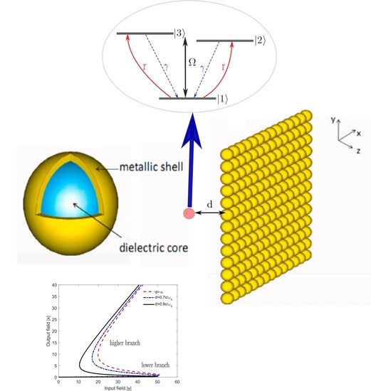
Figure 1. The three-level quantum V-system under study (a). A silica sphere coated with a gold nanoshell (b) and a two-dimensional square lattice of such spheres (c). The quantum sample (quantum emitter + array of spheres) is placed inside a unidirectional ring cavity (d).
Figure 1. The three-level quantum V-system under study (a). A silica sphere coated with a gold nanoshell (b) and a two-dimensional square lattice of such spheres (c). The quantum sample (quantum emitter + array of spheres) is placed inside a unidirectional ring cavity (d).

Figure 2. Plots of the input–output field curves for the quantum V-system. The dashed curve corresponds to the case of a medium of sole quantum emitters, i.e.,
, in which case, the decay rate is
. The dot-dashed (
) and solid (
) curves correspond a quantum-sample medium (emitter + metasurface) with
. We assumed that
,
,
and
.

Figure 3. Plots of the input–output field curves for the quantum sample (emitter + metasurface) for different values of emitter-metasurface distance
. We take
,
,
,
and
.
Figure 3. Plots of the input–output field curves for the quantum sample (emitter + metasurface) for different values of emitter-metasurface distance
. We take
,
,
,
and
.

Figure 4. Plots of the input–output field curves for the quantum sample (emitter + metasurface) for different distances d of the emitter from the plasmonic metasurface. We take
,
,
,
and
.
Figure 4. Plots of the input–output field curves for the quantum sample (emitter + metasurface) for different distances d of the emitter from the plasmonic metasurface. We take
,
,
,
and
.

Figure 5. Plots of the input–output field curves for the quantum sample (emitter + metasurface) for various values of the distance d. In (a), the incoherent pumping rate r varies from 0 to
; in (b), from
to
; and, in (c), from
to
. We take
,
,
and
and
.
Figure 5. Plots of the input–output field curves for the quantum sample (emitter + metasurface) for various values of the distance d. In (a), the incoherent pumping rate r varies from 0 to
; in (b), from
to
; and, in (c), from
to
. We take
,
,
and
and
.


Figure 6. (a) The population distributions
and
, (b) and the gain spectrum [
] (in units of
) of the quantum V-system as a function of the incoherent pumping r in the presence of a plasmonic nanostructure. We take here
, and
and
. The horizontal dotted line indicates the zero absorption limit, while the vertical dashed (solid) line indicates the limit for the incoherent pumping to achieve the population inversion
(gain
). Absorption takes place in
(the red zone in (b)). Gain without inversion appears in
(the green zone in (b)), while the lasing with inversion takes place when
(the blue zone in (b)).


|
Publisher’s Note: MDPI stays neutral with regard to jurisdictional claims in published maps and institutional affiliations.
|
© 2021 by the authors. Licensee MDPI, Basel, Switzerland. This article is an open access article distributed under the terms and conditions of the Creative Commons Attribution (CC BY) license (https://creativecommons.org/licenses/by/4.0/).
Share and Cite
MDPI and ACS Style
Hamedi, H.R.; Paspalakis, E.; Yannopapas, V. Effective Control of the Optical Bistability of a Three-Level Quantum Emitter near a Nanostructured Plasmonic Metasurface. Photonics 2021, 8, 285. https://doi.org/10.3390/photonics8070285
AMA Style
Hamedi HR, Paspalakis E, Yannopapas V. Effective Control of the Optical Bistability of a Three-Level Quantum Emitter near a Nanostructured Plasmonic Metasurface. Photonics. 2021; 8(7):285. https://doi.org/10.3390/photonics8070285
Chicago/Turabian StyleHamedi, Hamid R., Emmanuel Paspalakis, and Vassilios Yannopapas. 2021. "Effective Control of the Optical Bistability of a Three-Level Quantum Emitter near a Nanostructured Plasmonic Metasurface" Photonics 8, no. 7: 285. https://doi.org/10.3390/photonics8070285
Note that from the first issue of 2016, this journal uses article numbers instead of page numbers. See further details here.