US3338476A - Heating device for use with aerosol containers - Google Patents
Heating device for use with aerosol containers Download PDFInfo
- Publication number
- US3338476A US3338476A US504944A US50494465A US3338476A US 3338476 A US3338476 A US 3338476A US 504944 A US504944 A US 504944A US 50494465 A US50494465 A US 50494465A US 3338476 A US3338476 A US 3338476A
- Authority
- US
- United States
- Prior art keywords
- heater
- passageway
- temperature
- heat
- aerosol
- Prior art date
- Legal status (The legal status is an assumption and is not a legal conclusion. Google has not performed a legal analysis and makes no representation as to the accuracy of the status listed.)
- Expired - Lifetime
Links
Images


Classifications
-
- B—PERFORMING OPERATIONS; TRANSPORTING
- B65—CONVEYING; PACKING; STORING; HANDLING THIN OR FILAMENTARY MATERIAL
- B65D—CONTAINERS FOR STORAGE OR TRANSPORT OF ARTICLES OR MATERIALS, e.g. BAGS, BARRELS, BOTTLES, BOXES, CANS, CARTONS, CRATES, DRUMS, JARS, TANKS, HOPPERS, FORWARDING CONTAINERS; ACCESSORIES, CLOSURES, OR FITTINGS THEREFOR; PACKAGING ELEMENTS; PACKAGES
- B65D83/00—Containers or packages with special means for dispensing contents
- B65D83/14—Containers or packages with special means for dispensing contents for delivery of liquid or semi-liquid contents by internal gaseous pressure, i.e. aerosol containers comprising propellant for a product delivered by a propellant
- B65D83/72—Containers or packages with special means for dispensing contents for delivery of liquid or semi-liquid contents by internal gaseous pressure, i.e. aerosol containers comprising propellant for a product delivered by a propellant with heating or cooling devices, e.g. heat-exchangers
-
- H—ELECTRICITY
- H05—ELECTRIC TECHNIQUES NOT OTHERWISE PROVIDED FOR
- H05B—ELECTRIC HEATING; ELECTRIC LIGHT SOURCES NOT OTHERWISE PROVIDED FOR; CIRCUIT ARRANGEMENTS FOR ELECTRIC LIGHT SOURCES, IN GENERAL
- H05B3/00—Ohmic-resistance heating
- H05B3/10—Heater elements characterised by the composition or nature of the materials or by the arrangement of the conductor
- H05B3/12—Heater elements characterised by the composition or nature of the materials or by the arrangement of the conductor characterised by the composition or nature of the conductive material
- H05B3/14—Heater elements characterised by the composition or nature of the materials or by the arrangement of the conductor characterised by the composition or nature of the conductive material the material being non-metallic
- H05B3/141—Conductive ceramics, e.g. metal oxides, metal carbides, barium titanate, ferrites, zirconia, vitrous compounds
Definitions
- a heater-dispenser device for heating fluid materials passing therethrough is disclosed in which improved heating means is employed.
- the heating means comprises a solid state heater element having a temperature-resistivity curve which reflects low resistance values at relatively low temperatures with relatively small changes in resistance with increasing temperature until an anomaly point is reached at which point the resistance rapidly increases with slight temperature rise so that the heater element not only generates heat but also controls the amount of heat generated by effecting a thermal equilibrium at approximately the anomaly temperature.
- the heating element is in close thermal juxtaposition to the heat exchanger while in another embodiment the heat exchanger, heater and dispenser are formed integrally.
- This invention relates to an improved heating device for use with containers. More particularly, it relates to an improved device which can heat up a fluid medium issuing from a pressurized package.
- Pressurized containers have become Widely used for packaging and dispensing fluids and fluid-like materials. It is desirable to elevate the temperature of many of such materials, such as by way of example, windshield de-iceing fluids for automobiles, certain paints and varnishes, hot fudge and similar food items, shaving cream and so on.
- Aerosol containers employ a gas, such as Freon, under pressure to force the contents thereof out of the container when the discharge valve is opened. Since the containers are fabricated from relatively thin gauge materials it is important to keep the gas pressure at a safe level. Safe maximum temperatures, e.g. 120 F., have been determined for such containers since elevating the temperature of a gas in a constant volume increases the pressure thereof. Heaters used with aerosol containers, to be safe, must not cause the temperature of the container to approach these levels.
- a gas such as Freon
- Electric heaters in prior art devices have had certain I inherent limitations, to name a few, they have necessitated relatively complex, expensive constructions in order to provide for adequate safety and to keep the heating device in the environs of a desired temperature by turning on and off the heating element current by use of movable contacts. They have drawn relatively large amounts of power, line voltage variations have caused variations in heater temperature and extra parts'have been required to calibrate the heaters and regulate the temperature thereof.
- Another object is to provide an aerosol dispenserheater the temperature of which is self-regulating and insensitive to normal line voltage fluctuations.
- Another object of the invention is the provision of an aerosol dispenser-heater which is removablyattachable to the outlet of a pressurized container to heat the contents as they issue therefrom.
- my invention employs a solid state heating element, the temperature of which is self-regulating, and mounting the heater so that the fluid or fluid-like medium which issues from the aerosol container when the valve thereof is in the active or open position is heated while issuing therefrom.
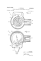
- FIG. 1 is a cross sectional side view of one embodiment of the invention, with part of the aerosol container broken away;
- FIG. 2 is a cross sectional view of FIG. 1;
- FIG. 3 is a cross sectional view of FIG. 1;
- FIG. 4 is a cross sectional view similar to FIG. 1 of a second embodiment of the invention.
- FIG. 5 is a cross sectional view taken along line 5-5 of FIG. 4;
- FIG. 6 is a cross sectional view of the heating element taken on line 6-6 of FIG. 5.
- a standard aerosol can 12 with a tubular discharge port 14 extending from an outlet valve mounts a heater-dispenser assembly 20'.
- Assembly 2b is composed of spiral-shaped base plate 22 having a central seating portion 24 shaped complementary to port 14 and into which port 14 is inserted.
- Aperture or ingress 26 is provided in portion 24 and is aligned with the bore in port 14 to permit passage of aerosol material therethrough as indicated by arrow 28.
- Base plate 22 is formed with spiral groove 30, best seen in FIG. 2, which provides communication between port 14 and spout or egress 32.
- a cover plate 40' is located in overlying relation to base plate 22 and encloses groove 30 to complete the spiral passageway. It will be seen that spout 32 is formed by portion 34 of base plate 22 and portion 36 of cover plate 40'.
- Cover plate 40 of a good thermally conductive material, is formed with a flange 42 about which base plate 22 is crimped as indicated at 44.
- Cover member 40 is formed with upstanding wall 46 extending therefrom which forms a cavity 48.
- a thin layer of an electrically insulating mataken along line 2-2 taken along line 3-3 terial 50, such as polyethylene terephthalate resin, is placed on the bottom surface of plate 40. This layer is preferably thin to keep thermal conductivity at an optimum.
- a piece of solid state PTC material, further defined infra, element 60, is located in close thermal contact with insulating layer 50 and cover 40.
- Upper and lower terminals, 62 and-64 respectively, are provided on opposite sides of element 60 and are attached in a conventional manner, as by soldering to an electrically conductive solder layer applied to said opposite sides.
- Tab portions 66 and 68 are provided on terminals 62 and 64 respectively and are crimped around wires 70, 72 of plug 74 as best seen in FIG. 3.
- Button 76 is placed on upper terminal 62 and electrically insulating potting material 80 encapsulates element 60 and base 7 8- of button 76.
- the electrical circuit may be traced from wire 70 of plug 74 to terminal 62 via tab 66, through element 60* to terminal 64 and finally to wire 72 of plug 74 via tab 68.
- Activation of the circuit is effected by connecting the opposite end of the cord composed of wires 70, 72 (the end which is not shown in the drawings) to normal house current. If it is deemed desirable a standard on-off switch may be incorporated into this cord.
- Heater-dispenser assembly 20 is shown in the active or open position in solid lines which results when a force F acts on button 76.
- the inactive or closed position is indicated in phantom lines.
- aerosol material issues under pressure from can 12 through grooves 30, as indicated by arrows 82 in FIG. 2.
- Cap member 84 is placed over assembly 20 and is provided with aperture 86 for reception of button 76 therethrough and is retained on can 12 by rib portion 88.
- Element 60 may be composed of any material which .has as a characteristic a large positive temperature coefiicient of resistance (PTC), that is, material in which the percent change in resistance per degree change in temperature in the so-called break or anomaly point is very large.
- PTC positive temperature coefiicient of resistance
- Polymers which can be cross-linked with carbon or other elements such as carbon black filled crosslinked polyethylene, e.g. No. 4510 obtainable from Cabot Corporation, 125 High Street, Boston, Massachusetts, are examples of one type of material.
- Another class of material is certain doped ceramics such as barium titanate doped with lanthanum, Ba La TiO
- one self-regulating heater element 60 was made using Ba ggqLa oogTlo g as follows.
- the raw materials used were reagent grades of barium carbonte (BaCO lanthanum carbonate La (CO H O and titanium dioxide (TiO These were weighed out to an accuracy of about ;.2S% to form stoichiometric mixtures, plus 0.1 mole percent excess TiO in order to assure the formation of a liquid phase during final firing. These materials were mixed and a sufficient amount of distilled water was added to form a 20% solid mixture by weight. This mixture was ball milled and dried. The dried product was powdered and calcined in order to convert the material into the desired doped compound (Ba La -TiO by firing at approximately 1100 C. in air and cooled.
- barium carbonte BaCO lanthanum carbonate La
- TiO titanium dioxide
- the material in the form of a porous cake, similar in texture and appearance to soft black-board chalk, was broken up and wet milled as above, dried comminuted and sieved from :40 to -270 (US. standard Sieves).
- the resulting powder was again immediately dried to drive ofi any moisture which might have been absorbed during comminution and sieving and finally pressed into the desired cylindrical shape using conventional closed die ceramic-pressing techniques on a hydraulic press.
- the resulting compacted powder body was fired to the ceramic state at about 1500" C. Further details regarding the preparation of similar PTC material may be found in copending application, filed Apr. 13, 1964, Ser. No. 359,370, assigned to the assignee of the instant invention.
- FIGS. 4-6 A second embodiment is shown in FIGS. 4-6 and indicated generally at 100. Aerosol can 12 is employed with port 14- as in the first described embodiment. In this embodiment the heat exchanger is formed integrally and as a part of the dispenser and heater. This heaterdispenser assembly is indicated at 110. A tube of an extrudable PTC material, such as carbon-filled crosslinked polyethylene referred to supra, is employed. As seen in FIG. 6- tube 120 is composed of an inner electrical insulating sleeve 122 of polyethylene and an outer sleeve 124- of PTC material. Clips and 132 are attached, as by crimping to sleeve 124.
- PTC material such as carbon-filled crosslinked polyethylene
- Tube 120 is preferably formed in a spiral and has ingress end 126 which is enlarged and formed only of electrically insulating sleeve 122 and in which is telescopically received port 14. Egress 127 of tube 120 is the dispenser end and may be fiared if desired. End 127 is also formed of inner sleeve 122. Electrically insulating material such as polyethylene, is molded around tube 120 and forms a cylindrical slab to which button 76 is attached. Cap 152 is placed over heater-dispenser assembly 110 and is provided with aperture 86 for reception of button 76 as in the FIGS. l-3 embodiment.
- the device is shown in solid lines in the active or open position whereby force F biases port 14 downwardly opening the aerosol can valve and permitting aerosol material to issue under pressure through the tube as indicated by arrows 28.
- the inactive or closed position is indicated by phantom lines.
- PTC materials useful in accordance with my invention are steep sloped materials having a low resistance in the cold state. Initially, when power is applied through the heating circuit relatively large currents are drawn and consequently high power and heat are dissipated. The resistance stays at a relatively low level as the temperature increases until an anomaly point is reached at which point the resistance rapidly increases with slight temperature rise. At the anomaly point an increase in temperature is accompanied by a proportionally much greater increase in resistivity. Concomitant with this increase in resistivity is a decrease in power showing that current level drops as the resistance increases thereby limiting the quantity of heat generated. As a result the heat generated always tends to balance the heat dissipated.
- the use of the PTC heating element provides an automatically controlled electrical heat input to the heat exchanger.
- the element resistance is low.
- Application of line voltage to the element will cause a substantial current flow with concomitant heat generation in the heating element.
- the element temperature reaches the temperature-resistance anomaly wherein the resistance increases very rapidly with temperature, current will be reduced by the increasing resistance to the point that termal equilibrium will result at approximately the anomaly temperature.
- a heating device constructed in accordance with my invention has a rapid warmup time, in the order of 30 seconds from room ambient employing a heating element designed to draw 200 watts from a cold start. It will then cut itself back to about 4 Watts of standby power. If the device is left connected to a source of power it will regulate its own temperature using only the low standby power.
- Another advantage of my invention is that voltage variations have very little eflect on performance. Typical line variations range from 95 to 135 volts and will effect the warmup-time slightly but has nearly no effect on the equilibrium temperature.
- the PTC element acts as a power regulator at the anomaly point, a voltage drop resulting in a current increase and vise versa.
- yet another advantage offered by my invention is that the device itself has no moving parts, no calibration is required, it is easy to seal and has long life.
- the PTC heater element provides extremely rapid warmup time because of the high initial heat input and followed very quickly by a reduction in heat input, when equilibrium temperature is attained, to standby power.
- the initial input was 200 watts. This stabilized at about 220 F. and reduced heat demand to 4 watts. Even after hours of continuous activation the top of the pressurized container was barely warm to the touch.
- a detachable power cord could be used together with a mechanical interlock which would require detachment of the power cord prior to use of the dispenser.
- the heat stored in the element and heat exchanger would heat the issuing contents of the container.
- a heater-dispenser device usable with aerosol containers comprising:
- said ingress adapted to communicate with the outlet port of said aerosol container whereby a voltage applied to said terminal causes the heater element to generate heat and approach a thermal equilibrium with heat loss thereby heating a fluid medium passing through said passageway.
- a device in which the heater element is composed of Ba La TiO;.;.
- a device in which the heater and the support defining the passageway are formed integrally.
- a device in which the PTC element is in the form of a tube, and said terminals are attached to opposite ends of said tube.
- a device in which the PTC element is composed of carbon black filled cross-linked polyethylene.
- a device further including a battery source electrically connected to said terminals.
- a device in which the tube is coiled into a spiral, said support consisting of an electrical insulating encapsulation, a sleeve of electrical insulating material located within said tube and extending axially beyond said PTC material, said egress serving as a nozzle, said ingress flared to receive therein the tubular discharge port of said aerosol container.
- a device further including manually operable means to move said device and said port to an active position whereby the contents of said container are released into said passageway.
- a device in which said support member is formed with a spiral-shaped groove, and further comprising:
- a device in which said heater element and terminal means are disc shaped, said terminals sandwiching said heater element therebetween forming a heater assembly, and said cover member formed with upstanding wall portions defining a cavity, said element and terminal mounted on said cover member in said cavity, and electrically and thermally insulating potting compound infilled over said heater assembly and between said assembly and said wall portion.
- a heater-dispenser device usable with aerosol containers comprising:
- a heater-dispenser device comprising:
- terminal means electrically connected to spaced portions of said heater element whereby a voltage applied to said terminal causes the heater element 7 as to generate heat and approach a thermal equilibrium 3,032,635 5/ 1962 Kraft 222I46 X with heat loss while maintaining an essentially con- 3,067,311 12/1962 Lacy-Hulbert 219504 X stant temperature. 3,069,528 12/ 1962 Gardner 219214 3,116,403 12/1963 Carter 222146 X References Cited 3,134,191 5/1964 Davis 222-146 X UN STATES PATENTS 3,215,818 11/ 1965 Deaton.
Description
Aug. 29, R967 L MARCOUX 3,338,4W5
EATING DEVICE FOR USE WITH AEROSOL CONTAINERS Filed Oct. 24, 1965 5 Sheets-Sheet 1 g- I l j 40 I I} I Minn. 2 25 min...
Aug. 29, 197 MARcoUX 9 9 EATING DEVICE FOR USE WITH AEROSOL CONTAINERS Filed Oct. 24, 1965 5 Sheets-5heet 2 i B 3",. L. MARCOUX 3,338AM HEATING DEVICE FOR USE WITH AEROSOL CONTAINERS Filed Oct. 24, 1965 5 Sheets-Sheet 3 United States Patent 3,338,476 HEATING DEVICE FOR USE WITH AEROSQL CONTAINERS Leo Marcoux, Pawtuclret, lRJL, assignor to Texas instruments incorporated, Dallas, Tex., a corporation of Delaware Filed (Pet. 24, 1965, Ser. No. 504,944 12 Claims. (Cl. 222-ll46) ABSTRACT OF THE DISCLOSURE A heater-dispenser device for heating fluid materials passing therethrough is disclosed in which improved heating means is employed. The heating means comprises a solid state heater element having a temperature-resistivity curve which reflects low resistance values at relatively low temperatures with relatively small changes in resistance with increasing temperature until an anomaly point is reached at which point the resistance rapidly increases with slight temperature rise so that the heater element not only generates heat but also controls the amount of heat generated by effecting a thermal equilibrium at approximately the anomaly temperature. In one embodiment the heating element is in close thermal juxtaposition to the heat exchanger while in another embodiment the heat exchanger, heater and dispenser are formed integrally.
This invention relates to an improved heating device for use with containers. More particularly, it relates to an improved device which can heat up a fluid medium issuing from a pressurized package.
Pressurized containers have become Widely used for packaging and dispensing fluids and fluid-like materials. It is desirable to elevate the temperature of many of such materials, such as by way of example, windshield de-iceing fluids for automobiles, certain paints and varnishes, hot fudge and similar food items, shaving cream and so on.
Various prior art devices have been designed for this purpose. Generally they have been of two basic types as exemplified by the United States Patent to Lannert, 2,873,351 issued Feb. 1959. Said patent discloses a heat exchanger which is attachable to the outlet of an aerosol container. Fluid medium is directed through said heat exchanger as it is released from the container and is thereby heated. The heat exchanger is heated by an electric heater in one embodiment and by hot water in another embodiment. My invention pertains to an improvement on the first-mentioned embodiment.
Aerosol containers employ a gas, such as Freon, under pressure to force the contents thereof out of the container when the discharge valve is opened. Since the containers are fabricated from relatively thin gauge materials it is important to keep the gas pressure at a safe level. Safe maximum temperatures, e.g. 120 F., have been determined for such containers since elevating the temperature of a gas in a constant volume increases the pressure thereof. Heaters used with aerosol containers, to be safe, must not cause the temperature of the container to approach these levels.
Electric heaters in prior art devices have had certain I inherent limitations, to name a few, they have necessitated relatively complex, expensive constructions in order to provide for adequate safety and to keep the heating device in the environs of a desired temperature by turning on and off the heating element current by use of movable contacts. They have drawn relatively large amounts of power, line voltage variations have caused variations in heater temperature and extra parts'have been required to calibrate the heaters and regulate the temperature thereof.
It is therefore an object of this invention to overcome the disadvantages mentioned supra and to provide a simple, inexpensive, reliable, sturdy, heating device which is easy to fabricate and useful with aerosol containers.
It is another object of this invention to provide a heating device useful with aerosol containers which results in minimal heat transfer to the container.
Another object is to provide an aerosol dispenserheater the temperature of which is self-regulating and insensitive to normal line voltage fluctuations.
It is yet another object to provide a dispenser-heater which has a short warmup time.
Another object of the invention is the provision of an aerosol dispenser-heater which is removablyattachable to the outlet of a pressurized container to heat the contents as they issue therefrom.
Briefly, my invention employs a solid state heating element, the temperature of which is self-regulating, and mounting the heater so that the fluid or fluid-like medium which issues from the aerosol container when the valve thereof is in the active or open position is heated while issuing therefrom.
The invention accordingly comprises the elements and combinations of elements, features of construction, and arrangements of parts which will be exemplified in the structures hereinafter described, and the scope of the application of which will be indicated in the appended claims.
In the accompanying drawings, in which two of the various possible embodiments of the invention are illustrated:
FIG. 1 is a cross sectional side view of one embodiment of the invention, with part of the aerosol container broken away;
FIG. 2 is a cross sectional view of FIG. 1;
FIG. 3 is a cross sectional view of FIG. 1;
FIG. 4 is a cross sectional view similar to FIG. 1 of a second embodiment of the invention;
FIG. 5 is a cross sectional view taken along line 5-5 of FIG. 4; and
FIG. 6 is a cross sectional view of the heating element taken on line 6-6 of FIG. 5.
Similar reference characters indicate corresponding parts throughout the several views of the drawings.
Dimensions of certain of the parts as shown in the drawings have been modified and/or exaggerated for the purpose of clarity of illustration.
Referring now to the drawings, and in particular to FIGS. 13 one embodiment of the invention is shown and designated generally by the reference numeral 10. A standard aerosol can 12 with a tubular discharge port 14 extending from an outlet valve mounts a heater-dispenser assembly 20'. Assembly 2b is composed of spiral-shaped base plate 22 having a central seating portion 24 shaped complementary to port 14 and into which port 14 is inserted. Aperture or ingress 26 is provided in portion 24 and is aligned with the bore in port 14 to permit passage of aerosol material therethrough as indicated by arrow 28. Base plate 22 is formed with spiral groove 30, best seen in FIG. 2, which provides communication between port 14 and spout or egress 32. A cover plate 40' is located in overlying relation to base plate 22 and encloses groove 30 to complete the spiral passageway. It will be seen that spout 32 is formed by portion 34 of base plate 22 and portion 36 of cover plate 40'. Cover plate 40, of a good thermally conductive material, is formed with a flange 42 about which base plate 22 is crimped as indicated at 44. Cover member 40 is formed with upstanding wall 46 extending therefrom which forms a cavity 48. A thin layer of an electrically insulating mataken along line 2-2 taken along line 3-3 terial 50, such as polyethylene terephthalate resin, is placed on the bottom surface of plate 40. This layer is preferably thin to keep thermal conductivity at an optimum.
A piece of solid state PTC material, further defined infra, element 60, is located in close thermal contact with insulating layer 50 and cover 40. Upper and lower terminals, 62 and-64 respectively, are provided on opposite sides of element 60 and are attached in a conventional manner, as by soldering to an electrically conductive solder layer applied to said opposite sides. Tab portions 66 and 68 are provided on terminals 62 and 64 respectively and are crimped around wires 70, 72 of plug 74 as best seen in FIG. 3. Button 76 is placed on upper terminal 62 and electrically insulating potting material 80 encapsulates element 60 and base 7 8- of button 76.
The electrical circuit may be traced from wire 70 of plug 74 to terminal 62 via tab 66, through element 60* to terminal 64 and finally to wire 72 of plug 74 via tab 68.
Activation of the circuit is effected by connecting the opposite end of the cord composed of wires 70, 72 (the end which is not shown in the drawings) to normal house current. If it is deemed desirable a standard on-off switch may be incorporated into this cord.
Heater-dispenser assembly 20 is shown in the active or open position in solid lines which results when a force F acts on button 76. The inactive or closed position is indicated in phantom lines. When force F is exerted, aerosol material issues under pressure from can 12 through grooves 30, as indicated by arrows 82 in FIG. 2. Cap member 84 is placed over assembly 20 and is provided with aperture 86 for reception of button 76 therethrough and is retained on can 12 by rib portion 88.
Element 60 may be composed of any material which .has as a characteristic a large positive temperature coefiicient of resistance (PTC), that is, material in which the percent change in resistance per degree change in temperature in the so-called break or anomaly point is very large. Polymers which can be cross-linked with carbon or other elements such as carbon black filled crosslinked polyethylene, e.g. No. 4510 obtainable from Cabot Corporation, 125 High Street, Boston, Massachusetts, are examples of one type of material. Another class of material is certain doped ceramics such as barium titanate doped with lanthanum, Ba La TiO As an example, one self-regulating heater element 60 was made using Ba ggqLa oogTlo g as follows.
The raw materials used were reagent grades of barium carbonte (BaCO lanthanum carbonate La (CO H O and titanium dioxide (TiO These were weighed out to an accuracy of about ;.2S% to form stoichiometric mixtures, plus 0.1 mole percent excess TiO in order to assure the formation of a liquid phase during final firing. These materials were mixed and a sufficient amount of distilled water was added to form a 20% solid mixture by weight. This mixture was ball milled and dried. The dried product was powdered and calcined in order to convert the material into the desired doped compound (Ba La -TiO by firing at approximately 1100 C. in air and cooled. The material, in the form of a porous cake, similar in texture and appearance to soft black-board chalk, was broken up and wet milled as above, dried comminuted and sieved from :40 to -270 (US. standard Sieves). The resulting powder was again immediately dried to drive ofi any moisture which might have been absorbed during comminution and sieving and finally pressed into the desired cylindrical shape using conventional closed die ceramic-pressing techniques on a hydraulic press. The resulting compacted powder body was fired to the ceramic state at about 1500" C. Further details regarding the preparation of similar PTC material may be found in copending application, filed Apr. 13, 1964, Ser. No. 359,370, assigned to the assignee of the instant invention.
A second embodiment is shown in FIGS. 4-6 and indicated generally at 100. Aerosol can 12 is employed with port 14- as in the first described embodiment. In this embodiment the heat exchanger is formed integrally and as a part of the dispenser and heater. This heaterdispenser assembly is indicated at 110. A tube of an extrudable PTC material, such as carbon-filled crosslinked polyethylene referred to supra, is employed. As seen in FIG. 6- tube 120 is composed of an inner electrical insulating sleeve 122 of polyethylene and an outer sleeve 124- of PTC material. Clips and 132 are attached, as by crimping to sleeve 124. An electrical conductor 134- connects clip 130 to one side of battery 138 and conductor 136 electrically connects clip 132 to the other side of battery 138. Switch 140 connected to conductor 136 and button 142 is used to open and close the circuit. Tube 120 is preferably formed in a spiral and has ingress end 126 which is enlarged and formed only of electrically insulating sleeve 122 and in which is telescopically received port 14. Egress 127 of tube 120 is the dispenser end and may be fiared if desired. End 127 is also formed of inner sleeve 122. Electrically insulating material such as polyethylene, is molded around tube 120 and forms a cylindrical slab to which button 76 is attached. Cap 152 is placed over heater-dispenser assembly 110 and is provided with aperture 86 for reception of button 76 as in the FIGS. l-3 embodiment.
As in the FIGS. 1-3 embodiment, the device is shown in solid lines in the active or open position whereby force F biases port 14 downwardly opening the aerosol can valve and permitting aerosol material to issue under pressure through the tube as indicated by arrows 28. The inactive or closed position is indicated by phantom lines.
PTC materials useful in accordance with my invention, are steep sloped materials having a low resistance in the cold state. Initially, when power is applied through the heating circuit relatively large currents are drawn and consequently high power and heat are dissipated. The resistance stays at a relatively low level as the temperature increases until an anomaly point is reached at which point the resistance rapidly increases with slight temperature rise. At the anomaly point an increase in temperature is accompanied by a proportionally much greater increase in resistivity. Concomitant with this increase in resistivity is a decrease in power showing that current level drops as the resistance increases thereby limiting the quantity of heat generated. As a result the heat generated always tends to balance the heat dissipated. If the heat demand is increased, the temperature of the PTC material tends to be reduced causing a drop in resistance. This results in a conomitant increase in current and hence increased generated power until once again the heat generated equals the heat dissipated with very little change in temperature.
The use of the PTC heating element provides an automatically controlled electrical heat input to the heat exchanger. At normal room temperature, the element resistance is low. Application of line voltage to the element will cause a substantial current flow with concomitant heat generation in the heating element. When the element temperature reaches the temperature-resistance anomaly wherein the resistance increases very rapidly with temperature, current will be reduced by the increasing resistance to the point that termal equilibrium will result at approximately the anomaly temperature.
A heating device constructed in accordance with my invention has a rapid warmup time, in the order of 30 seconds from room ambient employing a heating element designed to draw 200 watts from a cold start. It will then cut itself back to about 4 Watts of standby power. If the device is left connected to a source of power it will regulate its own temperature using only the low standby power.
As the aerosol container contents issues forth and draws heat from said element tending to cool the element, this Will be countered by an increase of power until it finally heats itself to equilibrium point.
Another advantage of my invention is that voltage variations have very little eflect on performance. Typical line variations range from 95 to 135 volts and will effect the warmup-time slightly but has nearly no effect on the equilibrium temperature. The PTC element acts as a power regulator at the anomaly point, a voltage drop resulting in a current increase and vise versa.
It will be seen that yet another advantage offered by my invention is that the device itself has no moving parts, no calibration is required, it is easy to seal and has long life.
The PTC heater element provides extremely rapid warmup time because of the high initial heat input and followed very quickly by a reduction in heat input, when equilibrium temperature is attained, to standby power. On a device constructed in accordance with this invention with 115 volts applied to the element the initial input was 200 watts. This stabilized at about 220 F. and reduced heat demand to 4 watts. Even after hours of continuous activation the top of the pressurized container was barely warm to the touch.
In the embodiments using line house current it is within the purview of the invention to use a step-down transformer in the line cord so that any electric grounding or short circuiting of the heating element or other electrical parts would not be dangerous.
Alternatively a detachable power cord could be used together with a mechanical interlock which would require detachment of the power cord prior to use of the dispenser. Thus the heat stored in the element and heat exchanger would heat the issuing contents of the container.
In view of the above it will be seen that the several objects of the invention are achieved and other advantageous results attained.
It is to be understood that the invention is not limited in its application to the details of construction and arrangement of parts illustrated in the accompanying drawings, since the inventions capable of other embodiments and of being practiced or carried out in various ways. Also, it is to be understood that the phraseology or terminology employed herein is for the purpose of description and not of limitation.
As many changes could be made in the above constructions without departing from the scope of the invention, it is intended that all matter contained in the above description or shown in the accompanying drawings, shall be interpreted as illustrative and not in a limiting sense, and it is also intended that the appended claims shall cover all such equivalent variations as come within the true spirit and scope of the invention.
What is claimed is:
1. A heater-dispenser device usable with aerosol containers comprising:
(a) a support with a passageway formed therein; said passageway having an ingress and an egress;
(b) a solid state heater element having a steep slope PTC temperature-resistivity curve in close thermal connection to said passageway and mounted by said support; and
(0) terminal means electrically connected to spaced portions of said heater element,
said ingress adapted to communicate with the outlet port of said aerosol container whereby a voltage applied to said terminal causes the heater element to generate heat and approach a thermal equilibrium with heat loss thereby heating a fluid medium passing through said passageway.
2. A device according to claim 1 in which the heater element is composed of Ba La TiO;.;.
3. A device according to claim 1 in which the heater and the support defining the passageway are formed integrally.
4. A device according to claim 1 in which the PTC element is in the form of a tube, and said terminals are attached to opposite ends of said tube.
5. A device according to claim 4 in which the PTC element is composed of carbon black filled cross-linked polyethylene.
6. A device according to claim 3 :further including a battery source electrically connected to said terminals.
7. A device according to claim 4 in which the tube is coiled into a spiral, said support consisting of an electrical insulating encapsulation, a sleeve of electrical insulating material located within said tube and extending axially beyond said PTC material, said egress serving as a nozzle, said ingress flared to receive therein the tubular discharge port of said aerosol container.
8. A device according to claim 7 further including manually operable means to move said device and said port to an active position whereby the contents of said container are released into said passageway.
9. A device according to claim 1 in which said support member is formed with a spiral-shaped groove, and further comprising:
(d) a cover plate of thermally conductive material overlying said grooves forming an internal passageway therethrough with an egress and an ingress, said heater element mounted in said cover plate in close thermal relation thereto; and
(e) terminals electrically connected to spaced portions of said heater element.
10. A device according to claim 1 in which said heater element and terminal means are disc shaped, said terminals sandwiching said heater element therebetween forming a heater assembly, and said cover member formed with upstanding wall portions defining a cavity, said element and terminal mounted on said cover member in said cavity, and electrically and thermally insulating potting compound infilled over said heater assembly and between said assembly and said wall portion.
11. A heater-dispenser device usable with aerosol containers comprising:
(a) a support member having a spiral-shaped groove;
(b) a cover plate of thermally conductive material overlying said support member and enclosing said grooves forming an internal passageway therewith with an egress and an ingress;
(c) a solid state heating element composed of PTC material having a steep slope temperature-resistivity curve supported on said cover plate in close thermal connection therewith;
(d) terminals electrically connected to two opposite faces of said element;
(e) electrical insulation interposed between said PTC element and said cover plate;
(f) said support member adapted to fit over a discharge port of an aerosol container with said ingress in communication with said port; and
(g) manually operable means to move said device and said port to an active position whereby the contents of said container is forced through said passageway and through said ingress and is heated by said element when voltage is applied to said terminal, said voltage causing said PTC element to generate heat and approach a thermal equilibrium with heat loss.
12. A heater-dispenser device comprising:
(a) a solid state heater element having a resistivity, temperature curve characterized by a portion of the curve having a relatively low resistance value, an anomaly point and a further portion displaying a positive temperature coeflicient of resistance and a relatively steep slope;
(b) a support having an internal passageway therein, said support mounting said heater element in close thermal relation; and
(c) terminal means electrically connected to spaced portions of said heater element whereby a voltage applied to said terminal causes the heater element 7 as to generate heat and approach a thermal equilibrium 3,032,635 5/ 1962 Kraft 222I46 X with heat loss while maintaining an essentially con- 3,067,311 12/1962 Lacy-Hulbert 219504 X stant temperature. 3,069,528 12/ 1962 Gardner 219214 3,116,403 12/1963 Carter 222146 X References Cited 3,134,191 5/1964 Davis 222-146 X UN STATES PATENTS 3,215,818 11/ 1965 Deaton. 1,654,551 1/ 1928 Muhleisen 219301 FOREIGN PATENTS 2,873,351 2/1959 Lannert 219214 1 2 4 419 1 19 2 France 2,914,221 11/ 1959 Rosenthal 222--146 11/19 0 Baker 219-504 X 10 RAPHAEL M. LUPO, Primary Examiner.
Claims (1)
1. A HEATER-DISPENSER DEVICE USABLE WITH AEROSOL CONTAINERS COMPRISING: (A) A SUPPORT WITH A PASSAGEWAY FORMED THEREIN; SAID PASSAGEWAY HAVING AN INGRESS AND AN EGRESS; (B) A SOLID STATE HEATER ELEMENT HAVING A STEEP SLOPE PTC TEMPERATURE-RESISTIVITY CURVED IN CLOSE THERMAL CONNECTED TO SAID PASSAGEWAY AND MOUNTED BY SAID SUPPORT; AND (C) TERMINAL MEANS ELECTRICALLY CONNECTED TO SPACED PORTIONS OF SAID HEATER ELEMENT, SAID INGRESS ADAPTED TO COMMUNICATE WITH THE OUTLET PORT OF SAID AEROSOL CONTAINER WHEREBY A VOLTAGE APPLIED TO SAID TERMINAL CAUSES THE HEATER ELEMENT TO GENERATE HEAT AND APPROACH A THERMAL EQUILIBRIUM WITH HEAT LOSS THEREBY HEATING A FLUID MEDIUM PASSING THROUGH SAID PASSAGEWAY.
Priority Applications (1)
| Application Number | Priority Date | Filing Date | Title |
|---|---|---|---|
| US504944A US3338476A (en) | 1965-10-24 | 1965-10-24 | Heating device for use with aerosol containers |
Applications Claiming Priority (1)
| Application Number | Priority Date | Filing Date | Title |
|---|---|---|---|
| US504944A US3338476A (en) | 1965-10-24 | 1965-10-24 | Heating device for use with aerosol containers |
Publications (1)
| Publication Number | Publication Date |
|---|---|
| US3338476A true US3338476A (en) | 1967-08-29 |
Family
ID=24008361
Family Applications (1)
| Application Number | Title | Priority Date | Filing Date |
|---|---|---|---|
| US504944A Expired - Lifetime US3338476A (en) | 1965-10-24 | 1965-10-24 | Heating device for use with aerosol containers |
Country Status (1)
| Country | Link |
|---|---|
| US (1) | US3338476A (en) |
Cited By (53)
| Publication number | Priority date | Publication date | Assignee | Title |
|---|---|---|---|---|
| US3400250A (en) * | 1966-01-03 | 1968-09-03 | Texas Instruments Inc | Heating apparatus |
| US3434089A (en) * | 1966-01-03 | 1969-03-18 | Texas Instruments Inc | Relay with voltage compensation |
| US3484378A (en) * | 1966-03-17 | 1969-12-16 | Carter Wallace | Aerosol heated shaving lather dispensing package |
| US3489976A (en) * | 1966-01-03 | 1970-01-13 | Texas Instruments Inc | Self-protected time delay relay |
| US3489884A (en) * | 1966-12-28 | 1970-01-13 | Texas Instruments Inc | Heated windshield wiper and blade therefor |
| US3493720A (en) * | 1967-12-19 | 1970-02-03 | Carter Wallace | Heater for aerosol foam-dispensing containers |
| US3553431A (en) * | 1968-05-27 | 1971-01-05 | Polaroid Corp | Control system for a heating station |
| US3564199A (en) * | 1968-12-30 | 1971-02-16 | Texas Instruments Inc | Self-regulating electric fluid-sump heater |
| US3582968A (en) * | 1968-12-23 | 1971-06-01 | Texas Instruments Inc | Heaters and methods of making same |
| US3805022A (en) * | 1972-10-10 | 1974-04-16 | Texas Instruments Inc | Semiconducting threshold heaters |
| US3891827A (en) * | 1973-01-12 | 1975-06-24 | Gad Jets Inc | Electrical heating device for use with aerosol containers |
| US3940591A (en) * | 1974-07-01 | 1976-02-24 | Texas Instruments Incorporated | Self-regulating electric heater |
| US3990987A (en) * | 1975-10-01 | 1976-11-09 | The United States Of America As Represented By The Administrator Of The National Aeronautics And Space Administration | Smoke generator |
| US3997083A (en) * | 1974-07-15 | 1976-12-14 | Dazey Products Company | Shaving lather heater and dispenser having heat storing element |
| US4056707A (en) * | 1975-10-06 | 1977-11-01 | Farnam Franklin C | Electrical heating device for use with aerosol containers |
| US4088269A (en) * | 1975-11-06 | 1978-05-09 | Vdo Adolf Schindling Ag | Electrically heated windshield washer spray nozzle assembly |
| US4121088A (en) * | 1976-10-18 | 1978-10-17 | Rosemount Inc. | Electrically heated air data sensing device |
| US4156127A (en) * | 1976-04-06 | 1979-05-22 | Daikin Kogyo Co., Ltd. | Electric heating tube |
| US4212425A (en) * | 1978-02-27 | 1980-07-15 | Vdo Adolf Schindling Ag. | Electrically heated windshield washer spray nozzle assembly |
| US4334141A (en) * | 1978-02-04 | 1982-06-08 | Firma Fritz Eichenauer | Combined electric water heating and vessel support plate for a beverage preparation device |
| US4343988A (en) * | 1978-02-04 | 1982-08-10 | Firma Fritz Eichenauer | Electrical resistance water heating device, particularly for beverage preparation machines |
| US4352008A (en) * | 1979-01-26 | 1982-09-28 | Firma Fritz Eichenauer | Electric heating device for heating the interior of a switch cabinet |
| US4371778A (en) * | 1978-09-15 | 1983-02-01 | Siemens Aktiengesellschaft | Electric heating device employing PTC heating element for preheating of heating oil |
| US4458137A (en) * | 1981-04-09 | 1984-07-03 | Rosemount Inc. | Electric heater arrangement for fluid flow stream sensors |
| US4493972A (en) * | 1980-12-29 | 1985-01-15 | Steinel Heinrich W | Electrically heated apparatus employing a PTC heater for liquifying a rod of binding material |
| US4508957A (en) * | 1982-09-24 | 1985-04-02 | Onofrio Rocchitelli | Thermostatically controlled electric heating device for motor vehicle glass washing fluid |
| US4560524A (en) * | 1983-04-15 | 1985-12-24 | Smuckler Jack H | Method of manufacturing a positive temperature coefficient resistive heating element |
| US4668857A (en) * | 1985-08-16 | 1987-05-26 | Belton Corporation | Temperature self-regulating resistive heating element |
| EP0290159A2 (en) * | 1987-04-21 | 1988-11-09 | TDK Corporation | PTC heating device |
| WO1994010512A1 (en) * | 1992-11-04 | 1994-05-11 | Watkins-Johnson Company | Gas heater for processing gases |
| WO1997003539A1 (en) * | 1995-07-07 | 1997-01-30 | Marvin Fabrikant | Heater for a liquid or gel container |
| US5786573A (en) * | 1995-07-07 | 1998-07-28 | Fabrikant; Marvin | Heater for shaving cream containers enabling vertical adjustment of the heater relative to the container |
| USD456654S1 (en) | 2000-11-27 | 2002-05-07 | S. C. Johnson & Son, Inc. | Dispenser for shaving product |
| US6415957B1 (en) | 2000-11-27 | 2002-07-09 | S. C. Johnson & Son, Inc. | Apparatus for dispensing a heated post-foaming gel |
| US20030142966A1 (en) * | 2002-01-29 | 2003-07-31 | Hygema Terry L. | Heated fluid dispenser |
| US6655552B2 (en) | 2000-08-09 | 2003-12-02 | Aiken Industries, Inc. | Heating and dispensing fluids |
| US20040065683A1 (en) * | 2002-08-02 | 2004-04-08 | Conair Corporation | Heated dispenser |
| US6782196B1 (en) | 2003-02-28 | 2004-08-24 | Valeo Electrical Systems, Inc. | Fluid heater with freeze protection |
| US20040170414A1 (en) * | 2003-02-28 | 2004-09-02 | Karl-Heinz Kuebler | Fluid heater control apparatus and method with overtemperature protection |
| US20040170411A1 (en) * | 2003-02-28 | 2004-09-02 | Karl-Heinz Kuebler | Fluid heater temperature control apparatus and method |
| US6789744B2 (en) | 2002-01-29 | 2004-09-14 | Valeo Electrical Systems, Inc. | Fluid heater with a variable mass flow path |
| US20040197094A1 (en) * | 2003-04-04 | 2004-10-07 | Amberg Michael T. | Fluid heater with compressible cover freeze protection |
| US20040264951A1 (en) * | 2003-06-27 | 2004-12-30 | Karl-Heinz Kuebler | Fluid heater with low porosity thermal mass |
| US20050019028A1 (en) * | 2003-07-25 | 2005-01-27 | Karl-Heinz Kuebler | Fluid heater with integral heater elements |
| US20050047768A1 (en) * | 2003-08-29 | 2005-03-03 | Valeo Electrical Systems, Inc. | Fluid heater with integral heater element ground connections |
| US6912357B2 (en) | 2002-01-29 | 2005-06-28 | Valeo Electrical Systems, Inc. | Fluid heater |
| US6952524B2 (en) | 2002-11-27 | 2005-10-04 | Valeo Electrical Systems, Inc. | Fluid heater temperature balancing apparatus |
| US20050279778A1 (en) * | 2002-09-10 | 2005-12-22 | Valois Sas | Fluid product dispensing valve and fluid product dispensing device comprising same |
| US20080067262A1 (en) * | 2006-09-14 | 2008-03-20 | S.C. Johnson & Son, Inc. | Aerosol Dispenser Assembly Having VOC-Free Propellant and Dispensing Mechanism Therefor |
| US20090038685A1 (en) * | 2000-12-02 | 2009-02-12 | Hill Peter J | Fluid delivery device |
| US20110265806A1 (en) * | 2010-04-30 | 2011-11-03 | Ramon Alarcon | Electronic smoking device |
| US11240880B1 (en) * | 2018-04-18 | 2022-02-01 | Elemental Scientific, Inc. | Heating system for spray chamber outlet |
| US11758949B2 (en) | 2018-09-07 | 2023-09-19 | Fontem Holdings 1 B.V. | Charging case for electronic smoking device |
Citations (11)
| Publication number | Priority date | Publication date | Assignee | Title |
|---|---|---|---|---|
| US1654551A (en) * | 1924-12-20 | 1928-01-03 | Schutte & Koerting Co | Fluid-heating device |
| US2873351A (en) * | 1958-03-14 | 1959-02-10 | Lannert Paul | Outlet heater for aerosol-type dispenser |
| US2914221A (en) * | 1955-08-16 | 1959-11-24 | Haloid Xerox Inc | Aerosol bomb development |
| US2962575A (en) * | 1958-11-12 | 1960-11-29 | King Seeley Corp | Electro-responsive system |
| FR1284419A (en) * | 1961-03-21 | 1962-02-09 | Siemens Elektrogeraete Gmbh | evaporator for refrigeration machines equipped with a defrosting device which can be electrically heated |
| US3032635A (en) * | 1960-10-03 | 1962-05-01 | August L Kraft | Heater and utilization system for converting small quantities of fusible solids |
| US3067311A (en) * | 1956-10-02 | 1962-12-04 | Lacy-Hulbert Cyril | Quick heated electric heater |
| US3069528A (en) * | 1959-01-30 | 1962-12-18 | Gardner Entpr Inc | Electrical heating unit |
| US3116403A (en) * | 1962-05-15 | 1963-12-31 | Alva B Carter | Material heating dispenser |
| US3134191A (en) * | 1962-05-29 | 1964-05-26 | Arthur L Davis | Fogging gun for insecticides and the like |
| US3215818A (en) * | 1963-04-29 | 1965-11-02 | Gen Motors Corp | Temperature control electric circuit |
-
1965
- 1965-10-24 US US504944A patent/US3338476A/en not_active Expired - Lifetime
Patent Citations (11)
| Publication number | Priority date | Publication date | Assignee | Title |
|---|---|---|---|---|
| US1654551A (en) * | 1924-12-20 | 1928-01-03 | Schutte & Koerting Co | Fluid-heating device |
| US2914221A (en) * | 1955-08-16 | 1959-11-24 | Haloid Xerox Inc | Aerosol bomb development |
| US3067311A (en) * | 1956-10-02 | 1962-12-04 | Lacy-Hulbert Cyril | Quick heated electric heater |
| US2873351A (en) * | 1958-03-14 | 1959-02-10 | Lannert Paul | Outlet heater for aerosol-type dispenser |
| US2962575A (en) * | 1958-11-12 | 1960-11-29 | King Seeley Corp | Electro-responsive system |
| US3069528A (en) * | 1959-01-30 | 1962-12-18 | Gardner Entpr Inc | Electrical heating unit |
| US3032635A (en) * | 1960-10-03 | 1962-05-01 | August L Kraft | Heater and utilization system for converting small quantities of fusible solids |
| FR1284419A (en) * | 1961-03-21 | 1962-02-09 | Siemens Elektrogeraete Gmbh | evaporator for refrigeration machines equipped with a defrosting device which can be electrically heated |
| US3116403A (en) * | 1962-05-15 | 1963-12-31 | Alva B Carter | Material heating dispenser |
| US3134191A (en) * | 1962-05-29 | 1964-05-26 | Arthur L Davis | Fogging gun for insecticides and the like |
| US3215818A (en) * | 1963-04-29 | 1965-11-02 | Gen Motors Corp | Temperature control electric circuit |
Cited By (74)
| Publication number | Priority date | Publication date | Assignee | Title |
|---|---|---|---|---|
| US3400250A (en) * | 1966-01-03 | 1968-09-03 | Texas Instruments Inc | Heating apparatus |
| US3434089A (en) * | 1966-01-03 | 1969-03-18 | Texas Instruments Inc | Relay with voltage compensation |
| US3489976A (en) * | 1966-01-03 | 1970-01-13 | Texas Instruments Inc | Self-protected time delay relay |
| US3484378A (en) * | 1966-03-17 | 1969-12-16 | Carter Wallace | Aerosol heated shaving lather dispensing package |
| US3489884A (en) * | 1966-12-28 | 1970-01-13 | Texas Instruments Inc | Heated windshield wiper and blade therefor |
| US3493720A (en) * | 1967-12-19 | 1970-02-03 | Carter Wallace | Heater for aerosol foam-dispensing containers |
| US3553431A (en) * | 1968-05-27 | 1971-01-05 | Polaroid Corp | Control system for a heating station |
| US3582968A (en) * | 1968-12-23 | 1971-06-01 | Texas Instruments Inc | Heaters and methods of making same |
| US3564199A (en) * | 1968-12-30 | 1971-02-16 | Texas Instruments Inc | Self-regulating electric fluid-sump heater |
| US3805022A (en) * | 1972-10-10 | 1974-04-16 | Texas Instruments Inc | Semiconducting threshold heaters |
| US3891827A (en) * | 1973-01-12 | 1975-06-24 | Gad Jets Inc | Electrical heating device for use with aerosol containers |
| US3940591A (en) * | 1974-07-01 | 1976-02-24 | Texas Instruments Incorporated | Self-regulating electric heater |
| US3997083A (en) * | 1974-07-15 | 1976-12-14 | Dazey Products Company | Shaving lather heater and dispenser having heat storing element |
| US3990987A (en) * | 1975-10-01 | 1976-11-09 | The United States Of America As Represented By The Administrator Of The National Aeronautics And Space Administration | Smoke generator |
| US4056707A (en) * | 1975-10-06 | 1977-11-01 | Farnam Franklin C | Electrical heating device for use with aerosol containers |
| US4088269A (en) * | 1975-11-06 | 1978-05-09 | Vdo Adolf Schindling Ag | Electrically heated windshield washer spray nozzle assembly |
| US4156127A (en) * | 1976-04-06 | 1979-05-22 | Daikin Kogyo Co., Ltd. | Electric heating tube |
| US4121088A (en) * | 1976-10-18 | 1978-10-17 | Rosemount Inc. | Electrically heated air data sensing device |
| US4334141A (en) * | 1978-02-04 | 1982-06-08 | Firma Fritz Eichenauer | Combined electric water heating and vessel support plate for a beverage preparation device |
| US4343988A (en) * | 1978-02-04 | 1982-08-10 | Firma Fritz Eichenauer | Electrical resistance water heating device, particularly for beverage preparation machines |
| US4212425A (en) * | 1978-02-27 | 1980-07-15 | Vdo Adolf Schindling Ag. | Electrically heated windshield washer spray nozzle assembly |
| US4371778A (en) * | 1978-09-15 | 1983-02-01 | Siemens Aktiengesellschaft | Electric heating device employing PTC heating element for preheating of heating oil |
| US4352008A (en) * | 1979-01-26 | 1982-09-28 | Firma Fritz Eichenauer | Electric heating device for heating the interior of a switch cabinet |
| US4493972A (en) * | 1980-12-29 | 1985-01-15 | Steinel Heinrich W | Electrically heated apparatus employing a PTC heater for liquifying a rod of binding material |
| US4458137A (en) * | 1981-04-09 | 1984-07-03 | Rosemount Inc. | Electric heater arrangement for fluid flow stream sensors |
| US4508957A (en) * | 1982-09-24 | 1985-04-02 | Onofrio Rocchitelli | Thermostatically controlled electric heating device for motor vehicle glass washing fluid |
| US4560524A (en) * | 1983-04-15 | 1985-12-24 | Smuckler Jack H | Method of manufacturing a positive temperature coefficient resistive heating element |
| US4668857A (en) * | 1985-08-16 | 1987-05-26 | Belton Corporation | Temperature self-regulating resistive heating element |
| EP0290159A2 (en) * | 1987-04-21 | 1988-11-09 | TDK Corporation | PTC heating device |
| EP0290159A3 (en) * | 1987-04-21 | 1989-11-23 | Tdk Corporation | Ptc heating device |
| WO1994010512A1 (en) * | 1992-11-04 | 1994-05-11 | Watkins-Johnson Company | Gas heater for processing gases |
| US5377300A (en) * | 1992-11-04 | 1994-12-27 | Watkins-Johnson Company | Heater for processing gases |
| WO1997003539A1 (en) * | 1995-07-07 | 1997-01-30 | Marvin Fabrikant | Heater for a liquid or gel container |
| US5786573A (en) * | 1995-07-07 | 1998-07-28 | Fabrikant; Marvin | Heater for shaving cream containers enabling vertical adjustment of the heater relative to the container |
| US6655552B2 (en) | 2000-08-09 | 2003-12-02 | Aiken Industries, Inc. | Heating and dispensing fluids |
| US6415957B1 (en) | 2000-11-27 | 2002-07-09 | S. C. Johnson & Son, Inc. | Apparatus for dispensing a heated post-foaming gel |
| USD456654S1 (en) | 2000-11-27 | 2002-05-07 | S. C. Johnson & Son, Inc. | Dispenser for shaving product |
| US20090038685A1 (en) * | 2000-12-02 | 2009-02-12 | Hill Peter J | Fluid delivery device |
| US6978914B2 (en) | 2001-11-27 | 2005-12-27 | S.C. Johnson & Son, Inc. | Valve elements for pressurized containers and actuating elements therefor |
| US6795645B2 (en) * | 2002-01-29 | 2004-09-21 | Dekko Technologies, Inc. | Heated fluid dispenser |
| US20030142966A1 (en) * | 2002-01-29 | 2003-07-31 | Hygema Terry L. | Heated fluid dispenser |
| US6912357B2 (en) | 2002-01-29 | 2005-06-28 | Valeo Electrical Systems, Inc. | Fluid heater |
| US6789744B2 (en) | 2002-01-29 | 2004-09-14 | Valeo Electrical Systems, Inc. | Fluid heater with a variable mass flow path |
| US20040065683A1 (en) * | 2002-08-02 | 2004-04-08 | Conair Corporation | Heated dispenser |
| US6978912B2 (en) | 2002-08-02 | 2005-12-27 | Conair Corporation | Heated dispenser |
| US7594596B2 (en) * | 2002-09-10 | 2009-09-29 | Valois S.A.S. | Fluid product dispensing valve and fluid product dispensing device comprising same |
| US20050279778A1 (en) * | 2002-09-10 | 2005-12-22 | Valois Sas | Fluid product dispensing valve and fluid product dispensing device comprising same |
| US6952524B2 (en) | 2002-11-27 | 2005-10-04 | Valeo Electrical Systems, Inc. | Fluid heater temperature balancing apparatus |
| US20040170414A1 (en) * | 2003-02-28 | 2004-09-02 | Karl-Heinz Kuebler | Fluid heater control apparatus and method with overtemperature protection |
| US6839509B2 (en) | 2003-02-28 | 2005-01-04 | Valeo Electrical Systems, Inc. | Fluid heater control apparatus and method with overtemperature protection |
| US6782196B1 (en) | 2003-02-28 | 2004-08-24 | Valeo Electrical Systems, Inc. | Fluid heater with freeze protection |
| US6850699B2 (en) | 2003-02-28 | 2005-02-01 | Valeo Electrical Systems, Inc. | Fluid heater temperature control apparatus and method |
| US20040170411A1 (en) * | 2003-02-28 | 2004-09-02 | Karl-Heinz Kuebler | Fluid heater temperature control apparatus and method |
| US20040170412A1 (en) * | 2003-02-28 | 2004-09-02 | Karl-Heinz Kuebler | Fluid heater with freeze protection |
| US20040197094A1 (en) * | 2003-04-04 | 2004-10-07 | Amberg Michael T. | Fluid heater with compressible cover freeze protection |
| US7190893B2 (en) | 2003-06-27 | 2007-03-13 | Valeo Electrical Systems, Inc. | Fluid heater with low porosity thermal mass |
| US20040264951A1 (en) * | 2003-06-27 | 2004-12-30 | Karl-Heinz Kuebler | Fluid heater with low porosity thermal mass |
| US20050019028A1 (en) * | 2003-07-25 | 2005-01-27 | Karl-Heinz Kuebler | Fluid heater with integral heater elements |
| US20050047768A1 (en) * | 2003-08-29 | 2005-03-03 | Valeo Electrical Systems, Inc. | Fluid heater with integral heater element ground connections |
| US20080067262A1 (en) * | 2006-09-14 | 2008-03-20 | S.C. Johnson & Son, Inc. | Aerosol Dispenser Assembly Having VOC-Free Propellant and Dispensing Mechanism Therefor |
| US9907338B2 (en) | 2010-04-30 | 2018-03-06 | Fontem Holdings 4 B.V. | Dosing control for an electronic smoking device |
| US11013269B2 (en) | 2010-04-30 | 2021-05-25 | Fontem Holdings 4 B.V. | Electronic smoking device with data exchange features |
| US9907337B2 (en) | 2010-04-30 | 2018-03-06 | Fontem Holdings 4 B.V. | Disabling control for an electronic smoking device |
| US20110265806A1 (en) * | 2010-04-30 | 2011-11-03 | Ramon Alarcon | Electronic smoking device |
| US10638795B2 (en) | 2010-04-30 | 2020-05-05 | Fontem Holdings 4 B.V. | Disabling control for an electronic smoking device |
| US10966462B2 (en) | 2010-04-30 | 2021-04-06 | Fontem Holdings 4 B.V. | Dosing control for an electronic smoking device |
| US10980276B2 (en) | 2010-04-30 | 2021-04-20 | Fontem Holdings 4 B.V. | Disabling control for an electronic smoking device |
| US9439455B2 (en) * | 2010-04-30 | 2016-09-13 | Fontem Holdings 4 B.V. | Electronic smoking device |
| US11026450B2 (en) | 2010-04-30 | 2021-06-08 | Fontem Holdings 4 B.V. | Dosing control for an electronic smoking device |
| US11154095B2 (en) | 2010-04-30 | 2021-10-26 | Fontem Holdings 4 B.V. | Control for an electronic smoking device |
| US11712067B2 (en) | 2010-04-30 | 2023-08-01 | Fontem Ventures B.V. | Disabling control for an electronic smoking device |
| US11406139B2 (en) | 2010-04-30 | 2022-08-09 | Fontem Holdings 4 B.V. | Charging pack for an electronic smoking device |
| US11240880B1 (en) * | 2018-04-18 | 2022-02-01 | Elemental Scientific, Inc. | Heating system for spray chamber outlet |
| US11758949B2 (en) | 2018-09-07 | 2023-09-19 | Fontem Holdings 1 B.V. | Charging case for electronic smoking device |
Similar Documents
| Publication | Publication Date | Title |
|---|---|---|
| US3338476A (en) | Heating device for use with aerosol containers | |
| US3476293A (en) | Aerosol heater with improved control means | |
| US4230935A (en) | Immersion heater | |
| US3644707A (en) | Safety heater for pressure dispensed product | |
| US3710985A (en) | Dispenser for providing warm lather for shaving | |
| US4358667A (en) | Cartridge-type electric immersion heating element having an integrally contained thermostat | |
| US3891827A (en) | Electrical heating device for use with aerosol containers | |
| US4045763A (en) | Sealed thermostatic heater | |
| US4821010A (en) | Thermal cutoff heater | |
| US4841127A (en) | Dual temperature hair curler utilizing a pair of PTC heaters | |
| US3032635A (en) | Heater and utilization system for converting small quantities of fusible solids | |
| US3947656A (en) | Temperature controlled cartridge heater | |
| US4072847A (en) | Electrical heater for heating liquid | |
| US3414705A (en) | Component oven | |
| US3400250A (en) | Heating apparatus | |
| CA1147002A (en) | Fail-safe thermostatically controlled circuit for use in apparatus for melting and dispensing thermoplastic material | |
| US6747251B1 (en) | Fast response heater for a glue gun | |
| US4100397A (en) | Thermostatically controlled electrical heater assembly | |
| US3896289A (en) | Aquarium water heater | |
| US4017713A (en) | Heater for severing plastic film | |
| US3749880A (en) | Apparatus for heating flowable material | |
| US3973100A (en) | Self-limiting electric hair curler heater | |
| US3277277A (en) | Thermostatically controlled electric immersion heater unit | |
| US6549136B2 (en) | Sensing and switching circuit employing a positive-temperature-coefficient sensing device | |
| US3105889A (en) | Bimetallic starter switch for gas discharge tubes |